Table Of Content

Design a minimum-order Chebyshev Type II filter with the same specifications as in the previous examples. You can use the info function to get information about the parameters used to design the filter. FIR filters are very attractive because they are inherently stable and can be designed to have linear phase. Nonetheless, these filters can have long transient responses and might prove computationally expensive in certain applications. The Targets menu of Filter Designer allows you to generate various types of code representing your filter.
Mastering the Art of RF Filter Design: A Comprehensive Guide
Building a Circuit to Measure the Effect of Noise on Audio Signals - Projects - All About Circuits
Building a Circuit to Measure the Effect of Noise on Audio Signals - Projects.
Posted: Sun, 10 Dec 2023 08:00:00 GMT [source]
Curious about how these essential components shape and refine signals in the realm of radio frequency communication? In this article, we will delve into the depths of RF filter design, exploring its fundamental principles, practical applications, and key considerations. Whether you are an engineering enthusiast or a professional seeking to expand your knowledge, this comprehensive guide will equip you with the essential understanding of RF filter design. In this example, you learned how to use designfilt to obtain a variety of lowpass FIR and IIR filters with different constraints and design methods. Designfilt can also be used to obtain highpass, bandpass, bandstop, arbitrary-magnitude, differentiator, and Hilbert designs.
Filter Image
A great reference example that is worth considering when designing any kind of filter. The right filter can transform a photo, making it look more bold, faded, blurred, saturated, or vibrant. Add a filter to bring out certain hues, refine the lighting, change the saturation or brightness, or apply a vignette around the edges. Filters can also enhance certain visual effects, like making the image more cold, warm, or vintage.
Bandpass Filters: Navigating the Frequency Spectrum
Impedance matching is a technique used to ensure maximum power transfer between the source and load. In RF filter design, impedance matching is crucial for minimizing signal reflections and optimizing filter performance. Techniques such as using transmission line structures, impedance transformers, or resonant circuits can be employed to achieve impedance matching and improve filter efficiency.
We design our filters to suit all kinds of pollution needs, indoor as well as outdoor: Dyson engineer - The Times of India
We design our filters to suit all kinds of pollution needs, indoor as well as outdoor: Dyson engineer.
Posted: Wed, 08 Nov 2023 08:00:00 GMT [source]
Identifying Interfering Frequencies
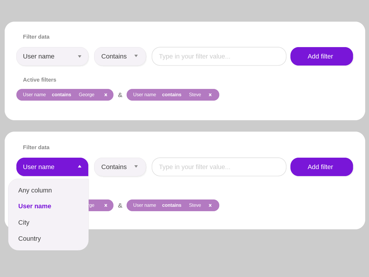
In fact, you could even use floating filters, so as a customer scrolls down the page, the filters are still accessible all the time. In these cases we need to rely on JavaScript to toggle between frozen and working states reliably, even if the data hasn’t come back from the server, or if it comes back slowly, or if it’s ill-formed. Every time we freeze the UI on a single input, we actively slow down our customers in expressing their intent. We actually make it a bit more cumbersome for them to specify what they are interested in, prioritizing the display of results over the input.
The Simplicity of Passive Filters
This is done by choosing a narrow ideal filter impulse response function, e.g., an impulse, and a weighting function which grows fast with the distance from the origin, e.g., the distance squared. An important parameter is the relative strength of the two weighting functions which determines in which domain it is more important to have a good fit relative to the ideal function. As stated by the Gabor limit, an uncertainty principle, the product of the width of the frequency function and the width of the impulse response cannot be smaller than a specific constant. This implies that if a specific frequency function is requested, corresponding to a specific frequency width, the minimum width of the filter in the signal domain is set.
The Versatility of Active Filters
To make your photos stand out on social media, you need to make visual edits or add filters to them — it's a requirement of great digital content in today's world. Starting with Instagram and VSCO, filters have become popular across social media apps and photography trends. But you don't need to download an app, get Photoshop, or pay for software - you can filter images online using Kapwing's online editor.
Related video of rf filter design
Careful attention should be given to the physical layout to reduce coupling and ensure proper signal integrity throughout the filter circuit. Using electromagnetic simulation tools and adhering to best practices in layout design can greatly enhance the filter’s performance. The center frequency of a bandpass filter represents the midpoint of the frequency range to be passed through the filter.
Practical Introduction to Digital Filter Design
In this section, we will delve into the design techniques for low-pass filters, discussing important parameters such as cutoff frequency, roll-off, and stopband attenuation. Since the characteristics of an ideal filter cannot be obtained, the goal of filter design is to approximate the ideal requirements within an acceptable tolerance. There are four types of approximations – namely Butterworth or maximally flat, Chebyshev, Bessel, and Elliptic approximations. For the prototype filters, maximally flat or Butterworth provides the flattest pass band response for a given filter order. In the Chebyshev method, sharper cutoff is achieved and the pass band response will have ripples of amplitude 1+k2. Bessel approximations are based on the Bessel function, which provides sharper cutoff, and Elliptic approximations results in pass band and stop band ripples.
After setting the design specifications, click the Design Filter button at the bottom of the GUI to design the filter. Add markers to the -3dB bandwidth points to determine the lower and upper cutoff frequencies. That is because the passband ripple varies between approximately -1.0 dB and -1.5 dB, which will slightly impact the definition of the lower and upper cutoff frequencies. Now that the parameters have been determined, create a model of the distributed bandpass filter in a new layout window. Use the MCFIL components for the coupled line sections and the MLIN components for the 50 Ω lines.

We therefore have some latitude in our design to compensate for tolerances of component values. When it comes to manufacturing RF filters, factors such as cost, scalability, and repeatability become important considerations. The chosen manufacturing process should be capable of producing filters with consistent performance and minimal variation.
The art of filter design necessitates compromises with respect to cutoff and roll off. They are the image parameter method, insertion loss method, and numerical synthesis. The image parameter method is an old and crude method, whereas the numerical method of synthesis is newer but cumbersome. The insertion loss method of filter design on the other hand is the optimum and more popular method for higher frequency applications. Digital filter implementation involves using digital signal processing techniques to achieve the desired filter characteristics.


No comments:
Post a Comment